CFH-36 IF-FILTER card MODIFICATIONS
 modification carte CFH-36.
5 IF FILTERS MODIFICATION :
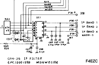
New schematic diagram:

Explanations:
- Solder the W1 jumper between A and C points.
- Unsolder the W2 jumper.
- Cut the P30-9 track (FM/ signal) going to the IC1 (74LS145) pin 5.
- Solder a small wire between the IC1 (74LS145) pin 6 and the P30-9 point (insulated).
- Solder a small wire between the IC1 (74LS145) pin 6 and the B point.
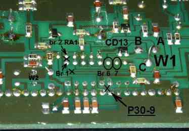
New circuit with modifications:

For more informations see the notices (V1.5 EPROM and after).
Top of the page.
SFM MODE MODIFICATIONS :
You need 4 diodes (1N914, 1N4148...) to make the FM and filters commutations.
In "Normal" FM mode, the 12 KHz IF filter is used.
In SFM mode, the WIDE filter (6 KHz) is used.
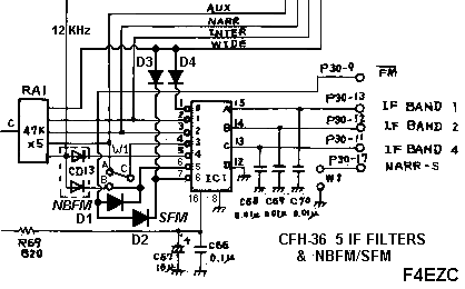
New schematic diagram:
 -
-

Explanations:
- Solder the W1 jumper between A and C points.
- Unsolder the W2 jumper.
- Cut the P30-9 track (FM/ signal) going to the IC1 (74LS145) pin 5.
- Insulate the IC1 (74LS145) pin 1. Cut the 2 tracks.
- Solder a small wire between the IC1 (74LS145) pin 6 and the B point.
- Solder the D1 diode between the IC1 (74LS145) pin 6 and the insulated P30-9 point (cathode on the pin 6).
- Solder the D2 diode between the IC1 (74LS145) pin 7 and the P30-9 point (cathode on the pin 7).
- Solder the D3 diode between the IC1 (74LS145) pin 7 and WIDE filter commutation track (cathode on the pin 7).
- Solder the D4 diode between the IC1 (74LS145) pin 1 and WIDE filter commutation track (cathode on the pin 1).
- Solder a small wire between the RA1 resistor pin 2 and WIDE filter commutation track.
New circuit with modifications:

For more informations see the notices (EPROM V2.0 et after).
Top of the page.
Home
F4EZC [email protected]
 FORM.
FORM.
.


 -
-


 FORM.
FORM.